


ELM99xxxxxCCMOS middle current voltage regulator
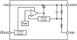
ELM99xxxxxC is CMOS middle current voltage regulator which consists of reference voltage source, error amplifier, low resistance output transistor, short-circuit protection circuit, thermal protection circuit, output voltage setting resisters and chip-enable circuit. ELM99 series is characterized with small input/output voltage difference (with its low resistance output transistor) and high load stability (with its high gain error amplifier). There are 3 types of CE selection of ELM99 series: non-chip enable function, “L” active and “H” active. The standard output voltages are 3.3V, 5.0V; these output voltages are fixed internally with high accuracy. ELM99 series can also be made as semi-custom IC within the range of 1.5V to 15.0V by 0.1V step.
| Output voltage range | 1.5V to 15.0V(by 0.1V) |
|---|---|
| Maximum output current | 300mA (Current is limited internally) |
| Stand-by Current consumption | Max.0.1µA(ELM99033xxC) |
| Input stability | Typ.0.1%/V(Iout=40mA) |
| Load stability | Typ.5mV(1mA<=Iout<=100mA) |
| Accuracy of output voltage | ±2.0% |
| Protection circuit | Thermal protection, Short protection |
| Package | SOT-89 SOT-89-5 SOT-23 SOT-25 |
| Datasheet | ELM99series |
- Application
- Battery operated devices
- Digital cameras
- Video recorders
- Reference voltage source
Absolute Maximum Ratings
| Parameter | Symbol | Limit | Unit |
|---|---|---|---|
| Input voltage | Vin | 20 | V |
| CE/CE Input voltage | Vce | Vss-0.3 to Vin+0.3 | V |
| Output voltage | Vout | Vss-0.3 to Vin+0.3 | V |
| Output current | Iout | 500(*1) | mA |
| Power dissipation (Ta=25°C) | Pd | SOT-89 (500(*2), 1000(*3)) SOT-89-5 (500(*2), 1000(*3)) SOT-23 (250(*2), 500(*3)) SOT-25 (250(*2), 600(*3)) | mW |
| Operating temperature | Top | -40 to +85 | °C |
| Storage temperature | Tstg | -55 to +125 | °C |
|
Block diagram
ELM99xxx1xC
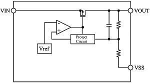
ELM99xxx2xC, ELM99xxx3xC